Java-tron Core Modules
Code Structure
Java-tron is a TRON network client developed based on the Java language. It implements all the functions mentioned in the TRON white paper, including consensus mechanism, cryptography, database, TVM virtual machine, network management, etc. We can run a TRON node by starting Java-tron. In this article, we will describe the code structure of Java-tron in detail, and introduce the functions of its various modules, to facilitate the subsequent code analysis and development of developers.
Java-tron adopts a modular code structure; the code structure is clear and easy to maintain and expand. Currently Java-tron is divided into 7 modules: protocol, common, chainbase, consensus, actuator, crypto, framework, the following introduces the functions of each module and its code organization.
protocol
For a distributed network such as blockchain, a concise and efficient data interaction protocol is very important. The protocol module defines:
- Inter-node communication protocol
- Communication protocol between modules within the node
- Agreement for Services Provided Externally
The above protocols adopt the Google Protobuf data exchange format. Compared with JSON and XML, the Google Protobuf format is more efficient and flexible and can be compiled by the ProtoBuf compiler to generate language-specific serialization and deserialization source code for the defined protocol files. Protobuf is the basis for java-tron to achieve cross-language and cross-platform.
protocol module's source code is located at: https://github.com/tronprotocol/java-tron/tree/develop/protocol , its directory structure is as follows:
|-- protos
    |-- api
    |   |-- api.proto
    |   |-- zksnark.proto
    |-- core
        |-- Discover.proto
        |-- Tron.proto
        |-- TronInventoryItems.proto
        |-- contract
protos/api/- The gRPC interface and data structure provided by the Java-tron node externallyprotos/core/- Data structure for communication between nodes and between modules within nodesDiscover.proto- Node discovers related data structuresTronInventoryItems.proto- Data structure related to block transferring between nodescontract/- Contract related data structuresTron.proto- Other important data structures, including accounts, blocks, transactions, resources, super representatives, voting, and proposals...
common
The common module encapsulates common components and tools, such as exception handling, metrics monitoring tools, etc which make it easy to use by other modules.
common module's source code is located at: https://github.com/tronprotocol/java-tron/tree/develop/common, its directory structure is as follows:
|-- /common/src/main/java/org/tron
    |-- common
    |   |-- args
    |   |-- config
    |   |-- entity
    |   |-- logsfilter
    |   |-- overlay
    |   |-- parameter
    |   |-- prometheus
    |   |-- runtime
    |   |-- setting
    |   |-- utils
    |-- core
        |-- config
        |-- db
        |-- db2
        |-- exception
common/prometheus- Prometheus metrics monitoringcommon/utils- The wrapper class of basic data typecore/config- Node configuration related classescore/exception- All exception handling related classes
chainbase
Chainbase is a database module. For probabilistic consensus algorithms such as PoW, PoS and DPoS, situations of switching to a new chain, however unlikely, are inevitable. Because of this, chainbase defines an interface standard supporting databases that can roll back. This interface requires databases to have a state rollback mechanism, a checkpoint-based disaster tolerant mechanism and so on.
In addition, the chainbase module features a well-designed abstract interface. Any database that implements the interface can be used for underlying storage on the blockchain, granting more flexibility to developers. LevelDB and RocksDB are two default implementations.
chainbase module's source code is located at: https://github.com/tronprotocol/java-tron/tree/develop/chainbase, its directory structure is as follows:
|-- chainbase.src.main.java.org.tron
    |-- common
    |   |-- bloom
    |   |-- error
    |   |-- overlay
    |   |-- runtime
    |   |-- storage
    |   |   |-- leveldb
    |   |   |-- rocksdb
    |   |-- utils
    |   |-- zksnark
    |-- core
        |-- actuator
        |-- capsule
        |-- db
        |   |-- RevokingDatabase.java
        |   |-- TronStoreWithRevoking.java
        |   |-- ......
        |-- db2
        |   |-- common
        |   |-- core
        |       |-- SnapshotManager.java
        |       |-- ......
        |-- net
        |-- service
        |-- store
common/- Common components, such as exception handling, tools, etcstorage/leveldb/Implemented the use of LevelDB as the underlying storage databasestorage/rocksdb/Implemented the use of RocksDB as the underlying storage database
-
core/- The core code of the chainbase module-
capsule/The encapsulation class of each data structure, such as AccountCapsule, BlockCapsule, etc. AccountCapsule is the encapsulation class of Account data structure, which provides modification and query of account data; BlockCapsule is the encapsulation class of Block data structure, which provides modification and query of block data.
-
store/Various databases, such as
AccountStore,ProposalStore, etc.AccountStoreis the account database, the database name isaccount, which stores all account information in the TRON network;ProposalStoreis the proposal database, and the database name isproposal, which stores all the proposal information in the TRON network. -
db/anddb2/Implemented rollbackable databases, including two rollbackable databases:
AbstractRevokingStorelocated in thedb/directory andSnapshotManagerlocated in thedb2/directory. Compared withAbstractRevokingStore,SnapshotManagerhas a more stable data rollback function and supports the extension of the underlying database. Therefore, Java-tron usesSnapshotManagerto roll back the database. Several important interfaces and implementation classes are as follows:RevokingDatabase.java- It is the interface of the database container, used to manage all rollbackable databases,SnapshotManageris an implementation of this interfaceTronStoreWithRevoking.java- It is the base class that supports rollbackable databases. All rollbackable databases are their implementations, such asBlockStore,TransactionStore, etc
-
consensus
The consensus mechanism is a crucial module in blockchains. Common ones are PoW, PoS, DPoS and PBFT, etc. While Paxos, Raft, etc, are applied to consortium blockchains and other trusted networks. The consensus mechanism should match the business scenario. For instance, PoW is not suitable for real-time games that are sensitive to consensus efficiency, while PBFT can make an optimized choice for exchanges demanding high real-time capability. In this sense, a replaceable consensus is a creative innovation and an essential link in building application-specific blockchains. Even star blockchain programs like Cosmos SDK are still at a stage where the application layer provides developers with limited autonomy and the consensus at the base level is subject to Tendermint. Therefore, the ultimate goal of the consensus module is to make consensus switch as easy as configuring parameters for application developers.
consensus module's source code is located at: https://github.com/tronprotocol/java-tron/tree/develop/consensus, its directory structure is as follows:
|-- consensus/src/main/java/org/tron/consensus
    |-- Consensus.java
    |-- ConsensusDelegate.java
    |-- base
    |   |-- ConsensusInterface.java
    |   |-- ......
    |-- dpos
    |-- pbft
ConsensusInterface:
start- start the consensus service with customizable startup parametersstop- stop the consensus servicereceiveBlock- define the consensus logic of receiving blocksvalidBlock- define the consensus logic of validating blocksapplyBlock- define the consensus logic of processing blocks
Currently, Java-tron implements DPOS consensus and PBFT consensus based on the ConsensusInterface interface, which is located in the dpos/ and pbft/ directories respectively. Developers can also implement the ConsensusInterface interface according to their own business needs to customize the consensus mechanism.
actuator
Ethereum was the first to introduce the virtual machine and define the smart contract. However, smart contracts are constrained in terms of their functions and not flexible enough to accommodate the needs of complex applications. This is one of the reasons why java-tron supports the creation of a chain of applications. For the reasons mentioned, java-tron includes a separate module, Actuator, offering application developers a brand new way of development. They can choose to implant their application codes into a chain instead of running them on virtual machines.
Actuator is the executor of transactions, while applications can be viewed as a cluster of different types of transactions, each of which is executed by a corresponding actuator.
actuator module's source code is located at: https://github.com/tronprotocol/java-tron/tree/develop/actuator, its directory structure is as follows:
|-- actuator/src/main/java/org/tron/core
    |-- actuator
    |   |-- AbstractActuator.java
    |   |-- ActuatorCreator.java
    |   |-- ActuatorFactory.java
    |   |-- TransferActuator.java
    |   |-- VMActuator.java
    |   |-- ......
    |-- utils
    |-- vm
actuator/- The executors of various types of transactions in the TRON network which define the processing logic of different types of transactions. For example,TransferActuatoris the processing class for transferring TRX, andFreezeBalanceV2Actuatoris the processing class for staking TRX to obtain resourceutils/- tools needed to execute transactionvm/- TRON virtual machine related code
Actuator module defines the Actuator interface, which includes 4 different methods:
execute- execute specific actions of transactions, such as state modification, communication between modules, logic execution, etc.validate- validate authenticity of transactionsgetOwnerAddress- acquire the address of transaction initiatorscalcFee- define the logic of calculating transaction fees
Depending on their businesses, developers may set up Actuator accordingly and customize the processing of different types of transactions.
crypto
Crypto is a relatively independent module, but it is also a very important module. Data security in Java-tron is almost entirely guaranteed by this module. Currently, SM2 and ECKey encryption algorithms are supported.
crypto module's source code is located at: https://github.com/tronprotocol/java-tron/tree/develop/crypto, its directory structure is as follows:
|-- crypto/src/main/java/org/tron/common/crypto
    |-- Blake2bfMessageDigest.java
    |-- ECKey.java
    |-- Hash.java
    |-- SignInterface.java
    |-- SignUtils.java
    |-- SignatureInterface.java
    |-- cryptohash
    |-- jce
    |-- sm2
    |-- zksnark
sm2andjce- Provide SM2 and ECKey encryption algorithm and signature algorithmzksnark- Provide a zero-knowledge proof algorithm
framework
The framework is the core module of java-tron and the entrance of the node. The framework module is responsible for the initialization of each module and business logic. The framework module includes the services provided externally, the node discovery and node management process related to the P2P network, and the block broadcasting and processing procedures.
framework module's source code is located at: https://github.com/tronprotocol/java-tron/tree/develop/framework, its directory structure is as follows:
|-- framework/src/main/java/org/tron
    |-- common
    |   |-- application
    |   |-- backup
    |   |-- logsfilter
    |   |-- net
    |   |-- overlay
    |   |   |-- client
    |   |   |-- discover
    |   |   |-- message
    |   |   |-- server
    |   |-- runtime
    |   |-- zksnark
    |-- core
    |   |-- Wallet.java
    |   |-- capsule
    |   |-- config
    |   |-- consensus
    |   |-- db
    |   |-- metrics
    |   |-- net
    |   |-- services
    |   |-- trie
    |   |-- zen
    |-- keystore
    |-- program
    |   |-- FullNode.java
    |-- tool
program/FullNode.java- It is the entry point of the program and initializes external HTTP, gRPC and json-rpc interface servicescore/services- Defines the externally provided services, its subdirectoryhttp/contains all http interface processing classes,json-rpc/contains all json-rpc interface processing classescommon/overlay/discover- Node discovery logiccommon/overlay/server- Node management and block synchronization logic among nodescore/net- Message processing, its subdirectory/serviceis transaction and block broadcasting, block fetching and synchronization logiccore/db/Manager.java- Transaction and block verification and processing logic
Summary
This article mainly introduces the code structure of Java-tron, as well as the function, location and directory structure of each functional module. Through this article, you will have a general understanding of the overall structure and key interfaces of Java-tron, which is helpful for subsequent code analysis and development.
ChainBase
Introduction
As we all know, the blockchain is essentially a non-tamperable distributed ledger, which is very suitable for solving the problem of trust. In reality, blockchain is often used for bookkeeping and transactions. For example, many applications use BTC, ETH, TRX, and other cryptos to carry out economic activities to ensure the openness and transparency of funds.
The realization of such an immutable distributed ledger is a very complex system engineering, involving many technical fields: such as p2p networks, smart contracts, databases, cryptography, consensus mechanisms, etc. Among them, the database is the basis of the underlying storage, and various blockchain teams are exploring the design and optimization of the database level.
The database module of Java-tron is also called the ChainBase module. This article mainly introduces some background knowledge and shows developers the implementation details of the ChainBase module by introducing logic such as transaction processing, state rollback, and data persistence.
Prerequisites
The database is an important part of the blockchain system. It stores all the data on the blockchain and is the basis for the normal operation of the blockchain system. Each fullnode stores a full amount of data, including block data, state data, etc. Java-tron uses the Account model to save the user's account state.
Account Models
There are currently two mainstream account models,
- UTXO
- Account Model
The UTXO model is stateless, makes it easier to process transactions concurrently, and has better privacy, but it is not programming-friendly.
In the Account Model, user data is stored in the corresponding account, and smart contracts are also stored in the account in the form of code. This model is more intuitive and easier for developers to understand. For programmability, flexibility, and other considerations, java-tron adopts the Account Model.
Consensus
The current mainstream consensus is PoW, PoS, DPoS, etc. PoW is proof of work, all nodes participate in the calculation of an expected hash result, and the node that first calculates the result has the right to produce a block, but as the computing power continues to increase, the energy consumption required to calculate the hash is also increasing. Moreover, large mining farms monopolize most of the computing power, which also goes against the original intention of decentralization.
To solve the problems faced by PoW, some people proposed PoS (Proof of Stake), which is simply understood as the more coins that the node holds, the greater the probability of obtaining the right to produce blocks, but this will lead to monopoly problems as well. In order to improve, DPoS (Delegated Proof of Stake) is proposed: the decentralization feature is guaranteed by the elected super representative, and the super representative is responsible for the block production in turn to improve the efficiency. Java-tron currently adopts the DPoS consensus mechanism.
To learn more, please refer to Delegated Proof of Stake.
Persistent Storage
There are certain differences between blockchain and traditional Internet business. The blockchain does not have particularly complex processing logic at the database level, but there are a large number of key-value read and write operations in the blockchain so there are higher requirements for data read and write performance.
Based on this consideration, java-tron uses LevelDB as the underlying data storage by default, and java-tron has a good architecture design. The interface-oriented programming mode makes the chainbase module have better scalability. All databases implemented the chainbase interface can be used as the underlying storage engine of java-tron. For example, in the chainbase v2 version, a database implementation based on RocksDB is provided.
Transaction Validation
As we all know, the blockchain mainly stores transaction data. Before introducing the chainbase module, you need to understand the transaction processing logic in java-tron.
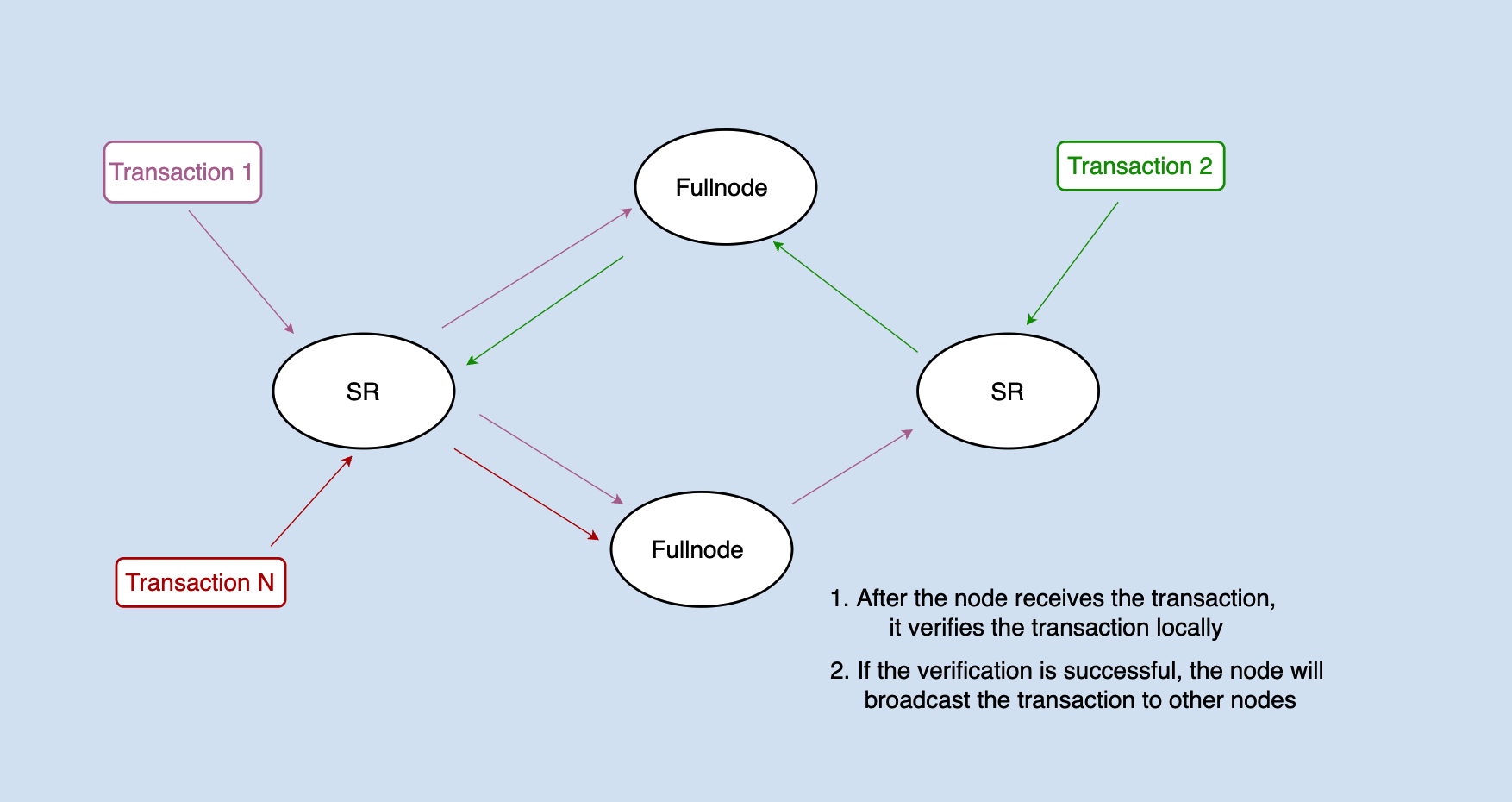
The transaction will be distributed to each node through network broadcast. After receiving the transaction, the node will first validate the signature of the transaction. If successful, the transaction needs to be pre-executed to determine whether the transaction is legal.
Note: The specific implementation of java-tron deviates from the above figure, and for the sake of convenience, this article collectively refers to the FullNode and SR as the nodes.
For example, to process a transfer transaction: user A transfers 100 TRX to user B, and it needs to validate whether user A has enough balance to make the transfer.
The account library in the database stores the account information of all users, including the user's balance information. How to judge whether this transfer transaction is legal? The logic of java-tron is: when a transaction is received from the network, the transaction operation will be executed immediately, that is, the account information will be modified in the local database: (accountA - 100TRX, accountB + 100TRX). If this operation can be executed successfully, it means that the transaction is legal at least in the current state, and can be packed into the block.
Glossary
SR: Super Representative, is responsible for block production.
FullNode: stores all block data, is responsible for transactions, block broadcasting and validation, and provides query services.
TRX: TRON native token.
State Rollback
Above we mentioned that java-tron validates whether the transaction is legal through pre-execution, but what we need to know is that the transaction is successfully validated on a certain node does not mean that the transaction has been successfully chained because the transaction has not been packed into the consensus blocks, there is a risk of being rolled back.
The consensus of java-tron follows a principle: that is, the transactions in the blocks that are approved by more than 2/3 of the SRs are the ones that are really successful on the chain. can also be understood as below,
- transactions are packed into a block
- the block is approved by more than 2/3 of the SRs
A transaction that satisfies the above two points is a successful transaction on the chain. A transaction in java-tron is finally confirmed through three stages,
- transaction validating
- transaction packing into the block
- block being accepted and applied
This also leads to a problem: in the implementation of java-tron, if a node validates the transaction, its database state changes accordingly. If the transaction is not packed into the block yet or the block it is packed into has not been approved by more than 2/3 of SR, the state of this node will be inconsistent with the state of the entire network.
Therefore, except for the processing transaction data in blocks approved by more than 2/3 SRs, all other data state changes resulting from transaction processing may need to be rolled back. There are three kinds of scenarios in total:
- after receiving a new block, roll back the state changes generated by transaction validation
- after producing a block, roll back the state changes generated by transaction validation
- if a forked takes place, roll back the state changes generated by the transactions of the blocks in the forked chain
The data state changes caused by these three scenarios may need to be rolled back and the following section explains why.
Rollback after Receiving a New Block
When receiving a new block, the node needs to roll back to the state at the end of the previous block and roll back all transactions validated afterward. As shown below,
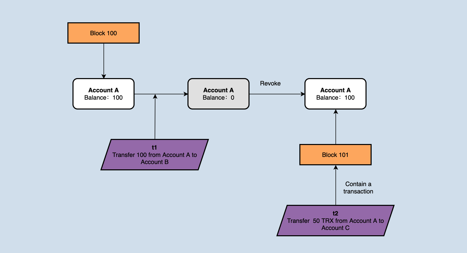
If the account balance of accountA is 100 at the block height is 1000, the node receives and validates a transaction 't1', in which accountA transfers 100TRX to accountB. After receiving the new block1001, the block contains a transaction 't2', in which accountA transfers 50TRX to accountC. In theory, t2 has been packed into the block, and the priority is higher than t1. However, if no operation is done, the validation of t2 will fail because accountA does not have enough balance. Therefore, after receiving the new block 1001, the state change generated by transaction t1 needs to be rolled back.
Rollback after Producing a New Block
First of all, readers may have a question: the validated transaction can be directly packed into the block, and it will not change the database state. Why is there a change in the database state?
Because java-tron does a secondary validation of the transaction when it is packed into the block. The secondary validation is due to the timeliness of the transaction. Still taking the above figure as an example, it can be seen from the figure, that after 1001 is received, the transaction t1 was rolled back, and the balance of accountA was deducted by 50. And then, it was the node's turn to produce a block, but t1 had become an illegal transaction at this time because the balance in accountA was not enough to transfer 100 TRX, it is not advisable to directly pack t1 into the block. So the transaction needs to be validated again, which is why the transaction needs to be validated twice when producing a block.
After the block is packed successfully, the node will broadcast the block to the network and apply the block locally. And the logic of applying will re-check the transactions in the block. So after the block is packed, a rollback operation still needs to be performed.
Rollback when Forking
This is the last rollback situation, and the blockchain will inevitably fork, especially the blockchain system based on DPoS with a faster block production speed that is more prone to fork.
java-tron maintains a data structure in memory as below,
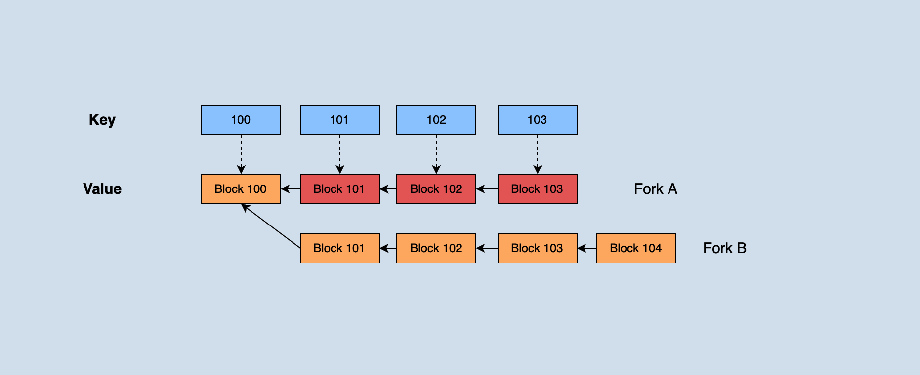
Java-tron holds all blocks that have not reached consensus recently. When a forked chain occurs, according to the longest chain principle: if the block height of the forked chain is greater than the current main chain block height, the forked chain needs to be switched to the main chain. Part of the blocks on the previous main chain needs to roll back up to their common parent blocks when switching, and then apply new main chain blocks sequentially from the parent block.
As shown in the figure, fork A in the dark part was originally the main chain. Because the height of fork B continues to grow and eventually exceeds the height of A, it is necessary to roll back the data in those three blocks with heights 1003, 1002, and 1001 in fork A. Then apply fork blocks 1001', 1002', 1003', and 1004' in B in sequence.
State Rollback Implementation
This chapter explains receiving and validating transactions, block production, validating and saving blocks from the perspective of code, to further analyze the chainbase module of java-tron. If there is no further declaration, the default description is dedicated to all the Fullnode (including SR).
Receiving Transactions
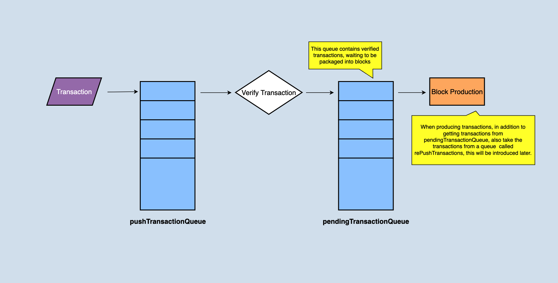
After the node receives a transaction, it puts the transaction into the local pushTransactionQueue cache queue by calling the pushTransaction(final TransactionCapsule trx) function of the manager class and validates the transaction at the same time. And the return of this method is sort of elegant:
- if validation is successful, ‘true' is returned
- for the transaction sent by the user to the node through the API, if the transaction validation fails, an exception will be returned to the user; for transactions received from other nodes through the network, exceptions will only be recorded locally
After the transaction validation is successful, the transactions without problems will be put into the pendingTransactionQueue, and the pendingTransactionQueue is responsible for providing the transaction set when producing blocks. If the node is an SR node, when producing a block, it will take out all or part of it from the pendingTransactionQueue (depending on how many transactions are in the pendingTransactionQueue) to generate a block.
Rollback when Receiving Blocks
A node would receive transactions broadcasted from other nodes before receiving a new block, the transactions need to be validated to determine whether they can be executed correctly. Validation means that the state needs to be changed, and a successful validation does not mean that the transaction will be finally executed, and it will be considered successful after packing into a block and the block become solidified. This step can be considered to filter out those obviously wrong transactions in advance. This is just validation. When a new block arrives, the state changed by transaction validations should be rolled back. Only the state changed when applying new blocks will not be rolled back.
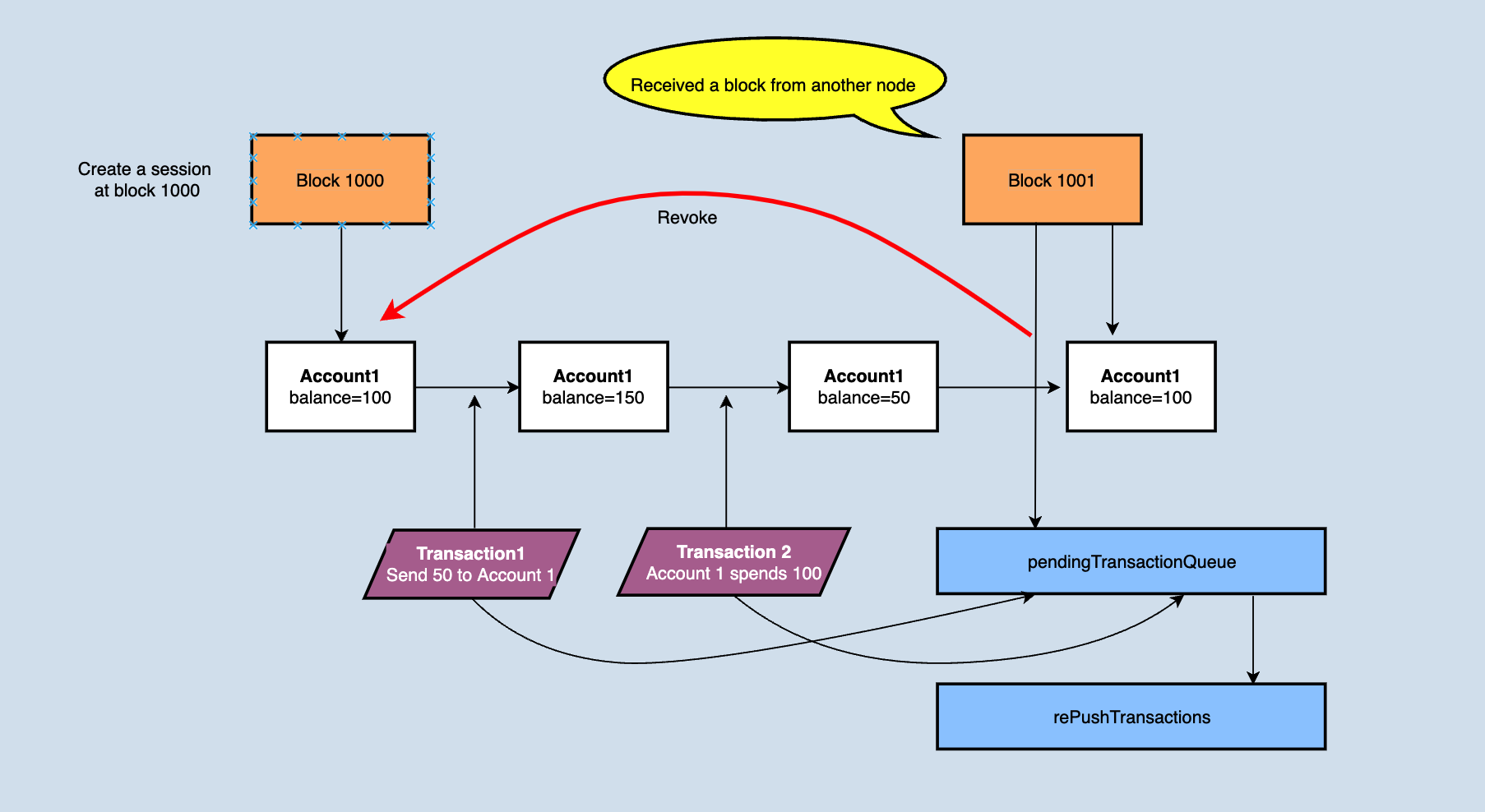
When rolling back, java-tron move the transactions in the pendingTransactionQueue to rePushTransactions, and clear the pendingTransactionQueue, see the figure for a detailed explanation.
Why does the pendingTransactionQueue need to be emptied after a new block arrives? First of all, it is clear that the pendingTransactionQueue queue is responsible for providing transaction data when generating blocks, that is to say, it stores validated transactions that can be directly packed into blocks. Since the new block will also change the account state, those validated transactions in pendingTransactionQueue may not pass the validation after applying the new block (the simplest example: a transaction in the new block is that accountA spends a part of the token, resulting in a transaction amount of accountA in the queue that is not enough to pay ). After the transaction is moved to rePushTransactions, a background thread will be responsible for re-validating the transaction in the queue. If nothing is wrong, it will be put into the pendingTransactionQueue again to provide data for block production.
There is a session object in Java-Tron. A session represents the change in the state of a block. The session object is mainly used for rollback. For example,rolling back the state to the state of the previous block needs to be operated throughout the session, as shown in the following figure,
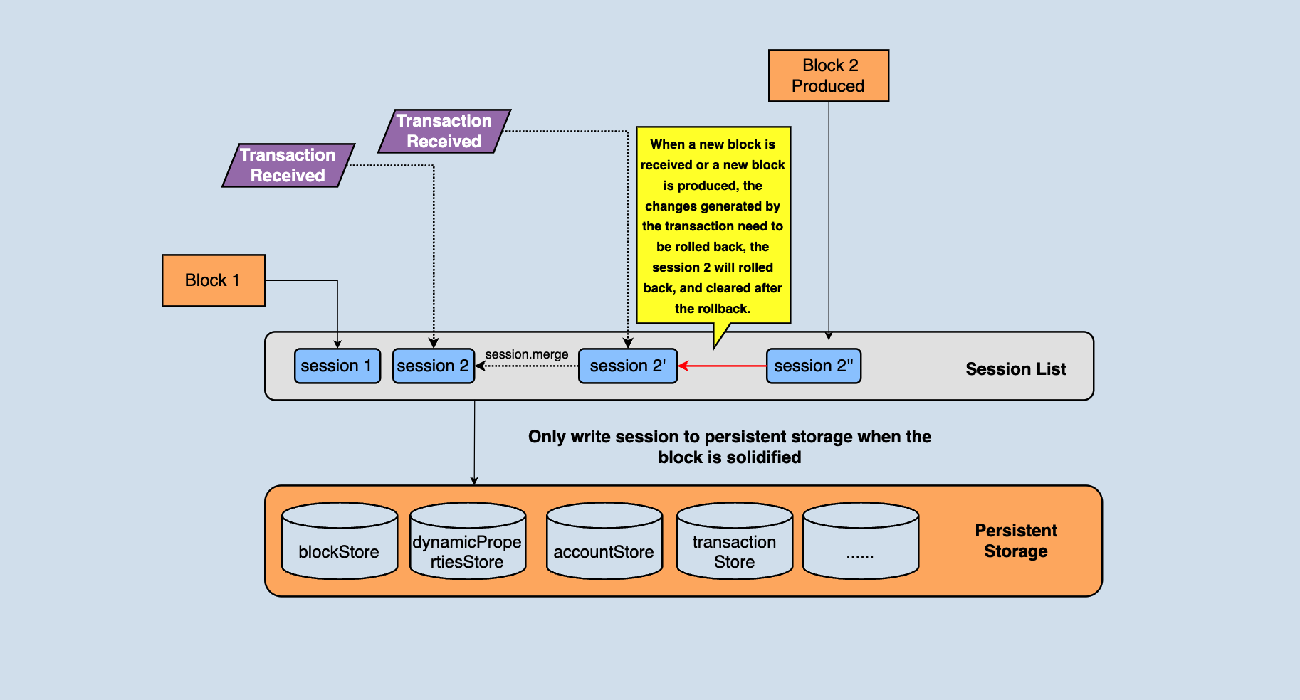
In the above figure, you can see that there are many different types of databases in persistent storage. These data are jointly organized into a complete blockchain. For example, blocks are stored in khasodb and blockStore, and account information is stored in accountStore...
The node maintains a session chain table, which stores the change information corresponding to the block/transaction, and the node can roll back through the change information. In the above figure, session1 is the status change of the current highest block. When a transaction is received, a new session2 will be generated. Each transaction that comes later will generate a temporary tmpSession, and after the transaction is validated, the tmpSession corresponded will be merged to session2. Before a new block is received again, all status changes generated by transaction validation will be saved in session2. When a new block arrives, directly execute the reset method of the session2 to roll back the state to the previous block.
Rollback when Producing Blocks
SR needs to roll back before producing blocks. The reasons are more complicated. Let's consider a scenario first:
- The pendingTransactionQueue stores the currently validated transactions, so when an SR node produces a block, it only needs to directly pack the transactions in the pendingTransactionQueue into the block, and then roll back the state to the state of the previous block after packing.
However, there is a problem with this scheme: if the SR node has just received and applied a new block, the pendingTransactionQueue will be cleared. At this time, it is the turn of the SR to pack the block, but there is no transaction in pendingTransactionQueue. Therefore, the real implementation is that not only reads transactions from pendingTransactionQueue when generating blocks but also reads transactions from rePushTransactions and puts them into blocks if there are few transactions in pendingTransactionQueue. The above analysis shows that transactions in rePushTransactions may not be possible to pass the validation, so the transactions need to be validated again. Due to this validation logic, the state needs to be rolled back before the block is produced.
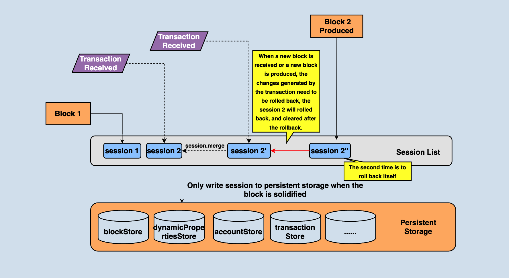
In the process of producing the block, the transaction will be validated again, so there will be a state change, but this is just block production, and the block needs to be broadcast as well, and those blocks who received the broadcast will actually change the state, so the state changes incurred by block production also need to be rolled back. As shown in the figure above, when the block production is completed, session2" needs to be rolled back.
Block Solidity
Java-tron adopts the DPoS consensus mechanism. The DPoS of java-tron is to vote for 27 nodes as block producers (also known as SR), SR has the right and obligation to produce blocks, and blocks approved by more than 2/3 of SR are considered to reach a consensus. These blocks, which are no longer rolled back are called solidified blocks. Only solidified blocks can be written to the database.
SnapshotManager in Java-Tron is the key entry to the storage module, holds references to all current business databases, and stores database references in a list. Each database instance supports adding a new layer of state set on its own called SnapshotImpl. It is an in-memory hashmap, multiple SnapshotImpl are associated in the form of a linked list, and one SnapshotImpl retains the data modification (in-merging or merging) involved in one state change, and SnapshotImpl is independent of each other. They are separated through this data structure, as shown in the following figure,
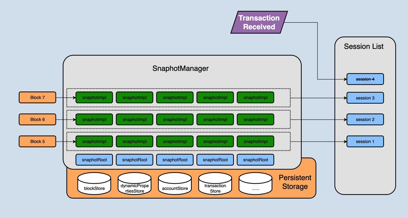
The SnapshotRoot in the above figure is the encapsulation class for the persistent database, which is responsible for storing the solidified data.
In the previous chapters, we talked about sessions. A session represents the changes of state in a block. In fact, a session contains the SnapshotImpl corresponding to each database. For example, all SnapshotImpl in the layer of block 5 in the above figure together constitutes the changes of block 5 to the entire database.
The changes generated after the node receives a new block will not be directly stored in the persistent storage (SnapshotRoot), but will first be stored in snapshotImpl. Each block received corresponds to a snapshotImpl. Continuously receiving blocks will lead to more and more snapshotImpl. When will they be written to persistent storage?
There are two variables in SnapshotManager: 'size' and 'maxSize'. Here we simply understand 'size' as how many layers of snapshotImpl are there currently in memory, and 'maxSize' represents the difference between the height of the current solidified block and the latest block.
This is obvious. If 'size' > 'maxSize', it means that the blocks corresponding to the first (size-maxSize) snapshotImpl are already solidified blocks, they can be placed on the disk, and then the snapshotImpl will be merged into the persistent storage. This ensures that snapshotImpl does not occupy too much memory, and also ensures that the solidified block can be persisted in time.
Atomicity
The database storage of Java-tron is slightly different from other public chains. For example, the Ethereum persistence layer uses only one database instance, and different types of data in Ethereum are distinguished by prefixes and stored in one database instance. However, Java-Tron currently stores data of different business types in its own database instances.
The two implementations have their own advantages. A single instance is easy to maintain and can be written uniformly, but the disadvantages are also obvious. For example, the amount of data in a single database continues to grow over time, and frequent access to some business databases may drag down the read-and-write performance of other businesses.
Multi-instance does not have the problem of the mutual influence of each business data read and write, and can configure different parameters according to their respective data volume and performance requirements to maximize performance, and can also independently split the database with a large amount of data. Alleviate data bloat problems. But there is a serious problem with multiple database instances: there is no native tool to support atomic writes among multiple database instances.
In order to ensure the atomic writing of multiple database instances, Java-Tron has added a checkpoint mechanism, which writes the changed data to the checkpoint uniformly before the multiple instances are placed on the disk. If an accident occurs in writing to multiple database instances, the changed data will be recovered from the checkpoint when the service is restarted to ensure the atomicity of writing.
The process of writing the snapshotImpl of the solidified block to the database in the previous section mainly includes two steps,
- create a checkpoint
- place snapshotImpl on disk
The operation of creating a checkpoint is more critical. A checkpoint is to persistently store the snapshotImpl in memory that needs to be written to the database in a tmp database (currently, the underlying implementation is leveldb and rocksdb). After the checkpoint is successfully created, the snapshotImpl will place on the disk. If the machine is down while placing, it will first search for the existence of tmp checkpoint data when the node restart. And if so, the data in the checkpoint will be played back to snapshotRoot.
A checkpoint data structure,
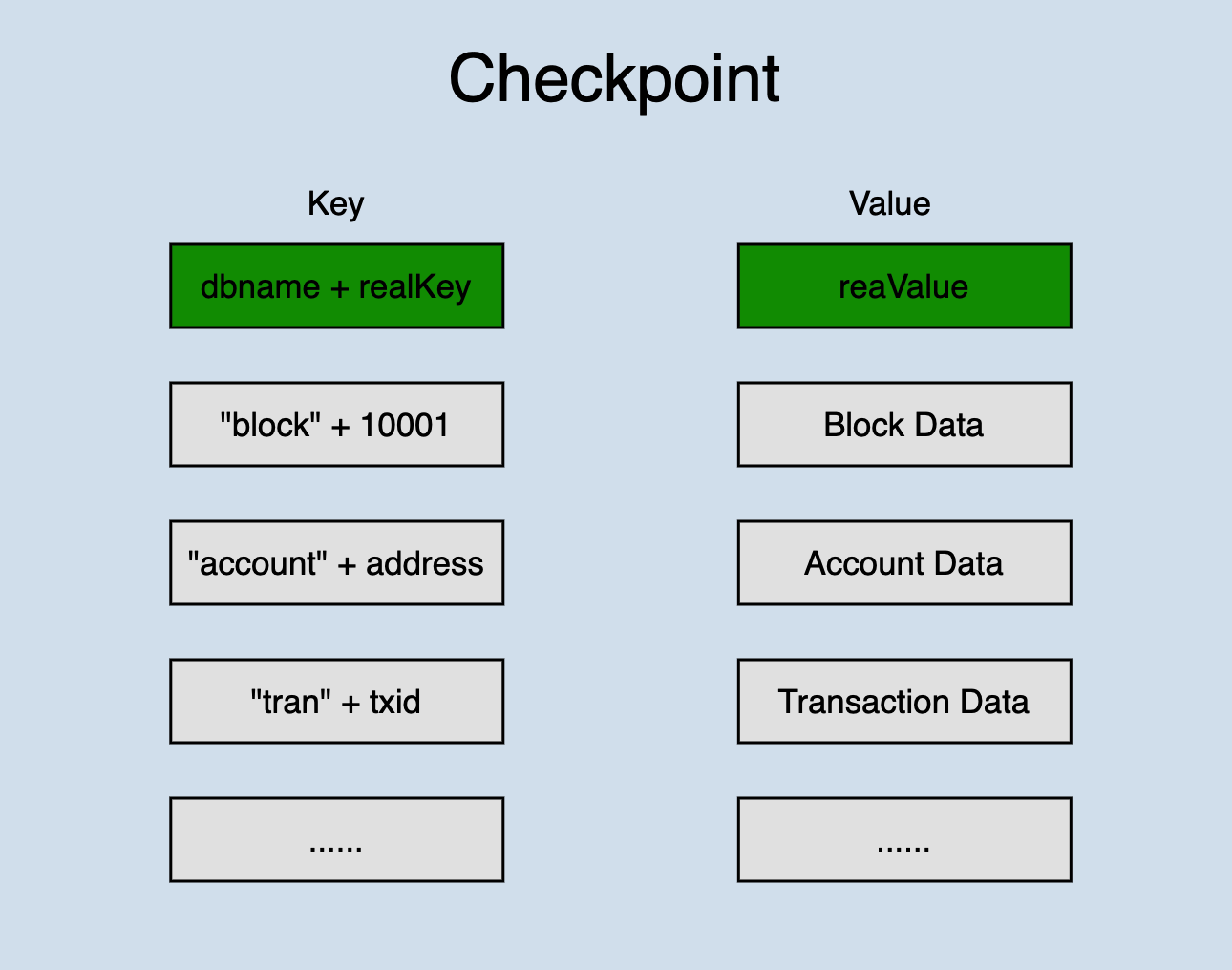
Checkpoint stores all data of a state change in one database. Different types of data are distinguished by prefixes. In order to ensure that all changed data can be placed on disk this time, the bottom layer of the database calls writeBatch() when writing.
This solution can be summarized as,
- the atomicity of writes cannot be guaranteed among multiple database instances, but a single database (most mainstream databases) supports atomic writes
- the data set that needs to be guaranteed to be written atomically is first written to a temporary database by atomic writing, and then the data is written to different database instances; if an accident occurs, it can be recovered through the data of the temporary database
Summary
This article analyzes the implementation details of rollback and database writing in the chainbase module through the processing flow of transactions and blocks and also analyzes the principle of atomic writing among multiple instances of the database to prevent database damage caused by accidental downtime. We hope that reading this article can help developers to further understand and develop the java-tron database.
Network
Overview
P2P is a distributed network in which participants in the network share a part of the hardware resources they own, such as processing power, storage capacity, network connection capacity, printers, etc. These shared resources need to be provided services and content by the network, which can be accessed by other peers directly without going through an intermediate entity. Participants in this network are both providers and acquirers of service and content.
Different from the traditional Client/Server central server structure, the status of each node in the P2P network is equal. While serving as a client, each node can also serve as a server to provide services to other nodes, which greatly improves the utilization of resources.
Blockchain Network
P2P is the network layer in the blockchain structure. The main purpose of the network layer is to realize information broadcast, verification and communication between nodes. The blockchain network is essentially a P2P network, and each node can both receive and generate information. Nodes keep communication by maintaining common blockchain data.
As the foundation of the blockchain, the P2P network brings the following advantages to the blockchain:
- Prevent single-point attack
- High fault tolerance
- Better compatibility and scalability
TRON Network
The architecture diagram of TRON is as follows:
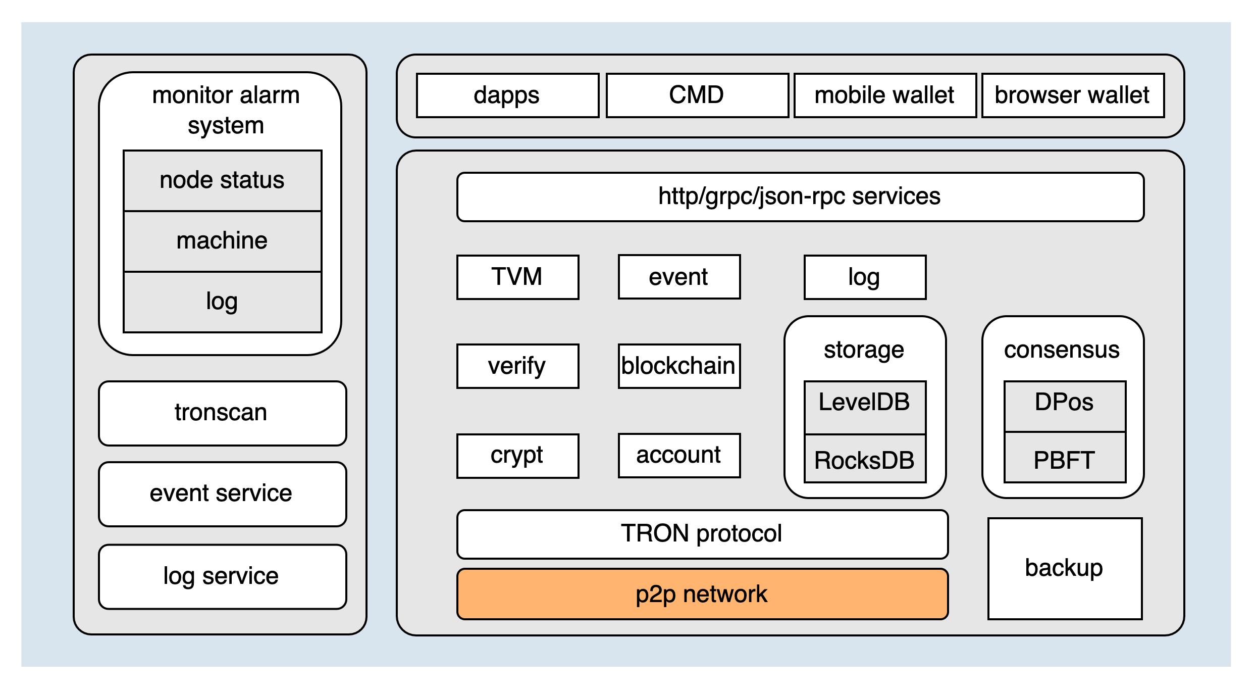
As the most fundamental module of TRON, the P2P network directly determines the stability of the entire blockchain network. The network module can be divided into the following four parts according to the function:
Below will separately introduce these four functional parts.
Node Discovery
Node discovery is the first step for nodes to access the blockchain network. The blockchain network is a structured P2P network which organizes all nodes in an orderly manner, such as forming a ring network or a tree-like network. Structured networks are generally implemented based on the DHT (Distributed Hash Table) algorithm. Specific implementation algorithms include Chord, Pastry, CAN, Kademlia and so on. The TRON network uses the Kademlia algorithm.
Kademlia Algorithm
Kademlia is an implementation of Distributed Hash Table (DHT), it is the core routing technology in the decentralized P2P network and can quickly find target nodes in the network without a central server.
For a detailed introduction to the algorithm, please refer to Kademlia.
Kademlia Implementation by TRON
The main points of the Kademlia algorithm implemented by TRON are as follows:
- Node ID: Randomly generated 512bit ID
- Node Distance: The node distance is obtained through the XOR operation of two nodes' ID. The formula is:
Node distance = 256 - the number of leading 0s in the node ID XOR result, if the calculation result is negative, the distance is equal to 0. - K-Bucket: The node routing table. According to the distance between the nodes, the remote nodes are divided into different buckets. The remote nodes with the same distance as the current node are recorded in the same bucket, and each bucket can accommodate up to 16 nodes. According to the calculation formula of node distance, it can be seen that the Kademlia algorithm implemented by TRON maintains a total of 256 buckets.
The node discovery protocol of TRON includes the following four UDP messages:
DISCOVER_PING- used to detect if a node is onlineDISCOVER_PONG- used in response toDISCOVER_PINGmessageDISCOVER_FIND_NODE- used to find other nodes closest to the target nodeDISCOVER_NEIGHBORS- used in response toDISCOVER_FIND_NODEmessage, will return one or more nodes, up to 16
Initialize K-Buckets
After the node is started, it will read the seed nodes configured in the node configuration file and the peer nodes recorded in the database, and then send DISCOVER_PING message to them respectively. If the reply message DISCOVER_PONG from a peer is received, and at the condition that the K bucket is not full, it will then write the peer node into the K bucket; But if the corresponding bucket has already been full (that is the bucket has reached 16 nodes), it will challenge to the earliest node in the bucket. If the challenge is successful, the old node will be deleted, and the new node will be added to the K bucket. That is the K bucket initialization process, then the node discovery process is performed.
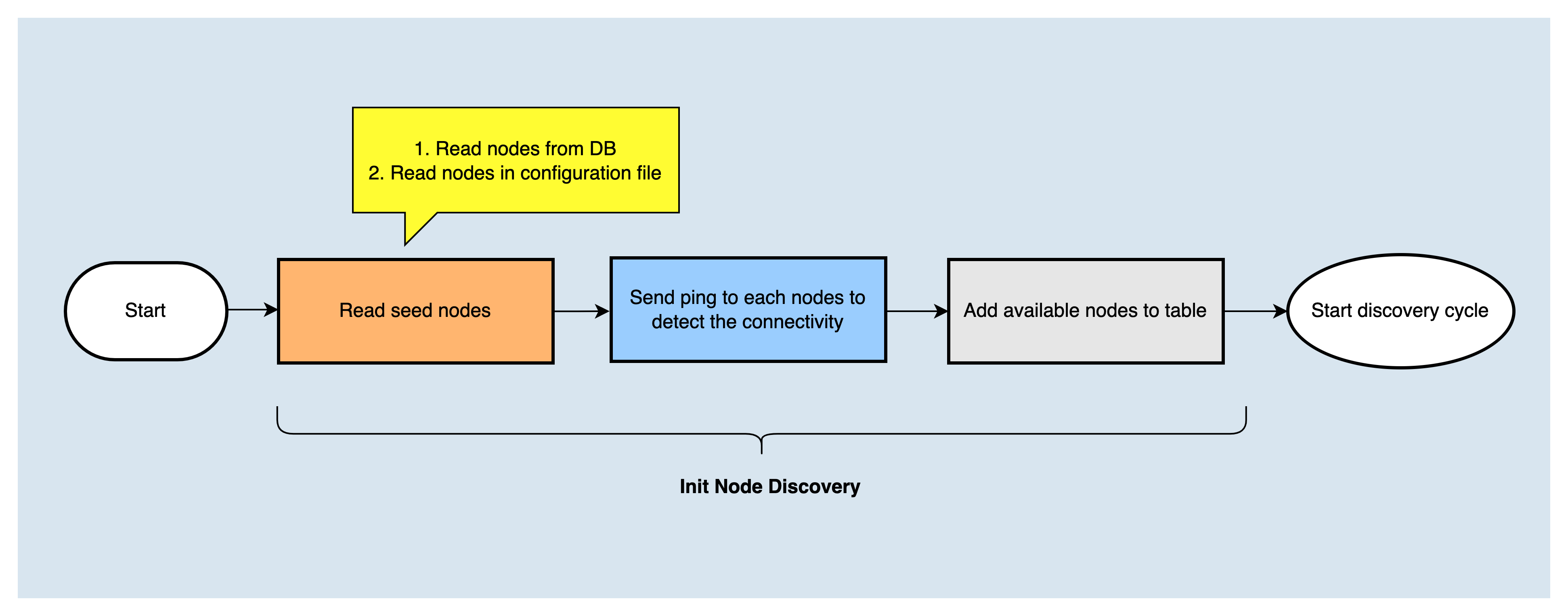
Send DISCOVER_FIND_NODE to Find More Nodes
The node discovery service will start two scheduled tasks (DiscoverTask and RefreshTask) to periodically perform the node discovery process to update k buckets.
DiscoverTaskis to discover more nodes that are closer to myself. It is executed every 30s. The execution flow is as follows: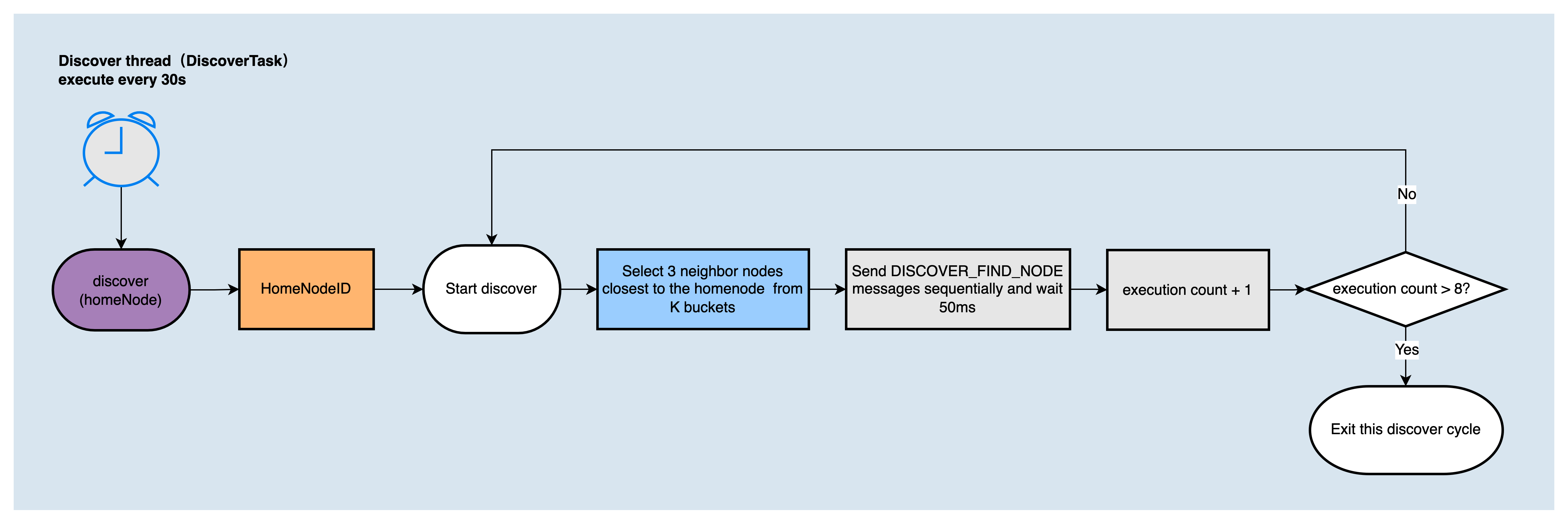
RefreshTaskis to expand the local k-bucket by random node ID, that is, to find nodes that are closer to the random node ID. It is executed every 7.2s. The execution process is as follows: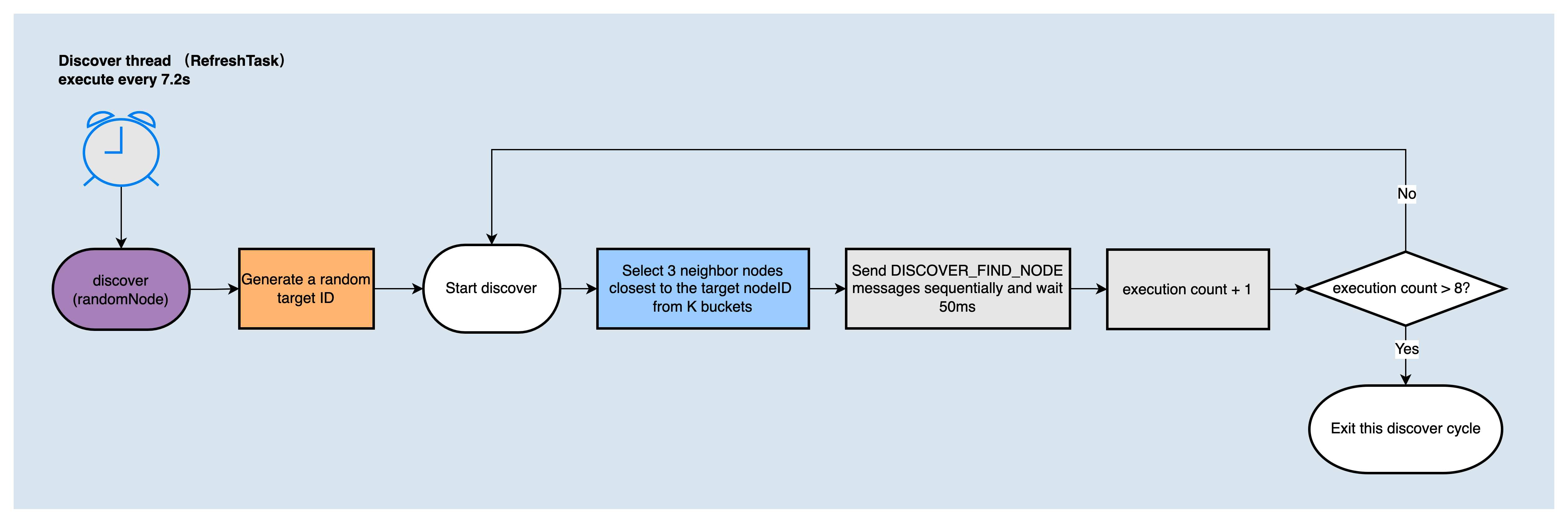
The node discovery algorithm used in DiscoverTask and RefreshTask will be executed 8 rounds in one call, and each round sends DISCOVER_FIND_NODE message to the 3 nodes closest to the target node ID in the K bucket, and waits for a reply.
Receive Neighbors' Messages and Update K Bucket
When the local node receives the DISCOVER_NEIGHBORS message replied by the remote node, it will send the DISCOVER_PING message to the received neighbor node in turn, and then if it receives the reply message DISCOVER_PONG, it will judge whether the corresponding K-bucket is full, if the K-bucket is not full, it will add the new node to the K bucket, if the K bucket is full, it will challenge one of the nodes, if the challenge is successful (send a DISCOVER_PING message to the old node, if it fails to receive the reply message DISCOVER_PONG, the challenge is successful, otherwise the challenge fails), the old node will be deleted from the K bucket, and the new node will be added to the K bucket.
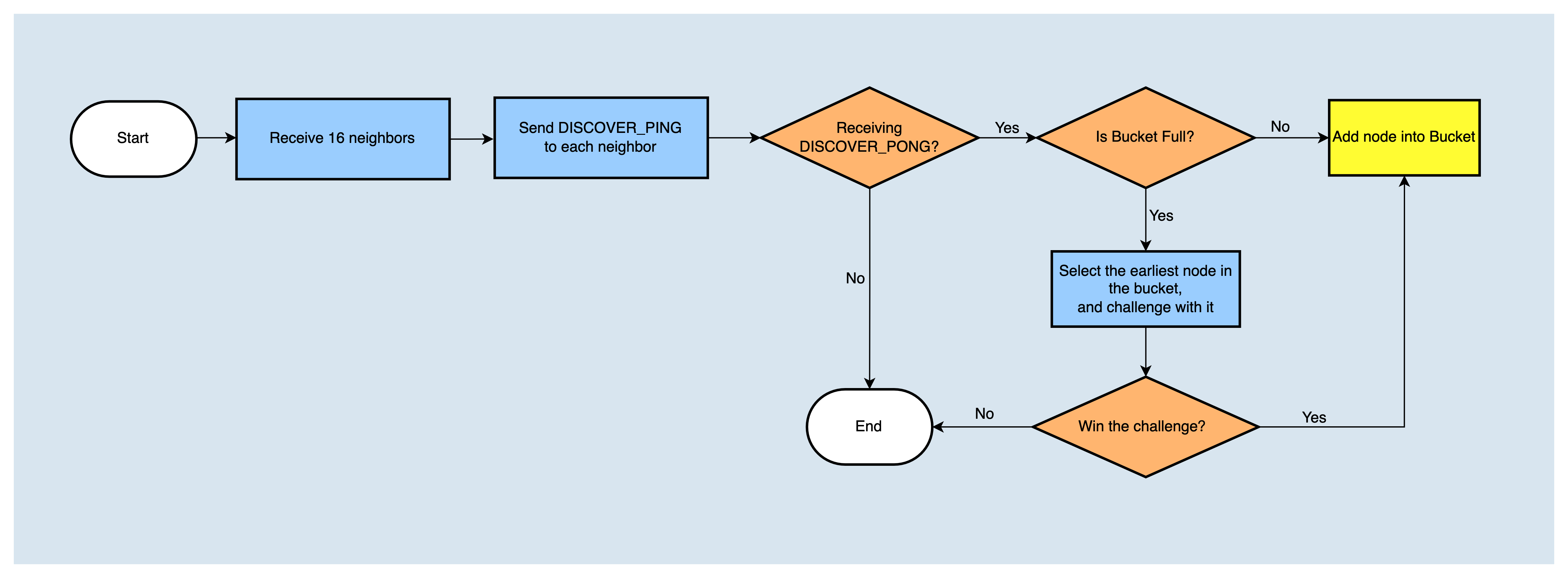
Nodes periodically perform node discovery tasks, continuously update K-buckets, and build their own node routing tables. The next step is to establish a connection with nodes.
Node Connection
Before understanding how to establish a TCP connection between nodes, we need to first understand the peer node type.
Peer Node Management
The local node needs to manage and classify peer nodes for efficient and stable node connection. Remote nodes can be divided into the following categories:
- Active nodes: specified in the configuration file. After the system starts, it will actively establish connections with the nodes. If the connection fails to be established, it will retry in each scheduled TCP connection task.
- Passive nodes: specified in the configuration file. The local node will passively accept connections from them.
- Trust nodes: specified in the configuration file, both Active nodes and Passive nodes are trusted nodes. When receiving a connection request from a trusted node, some other condition checks are skipped and the request is accepted directly.
- BadNodes: When an abnormal protocol packet is received, the sending node will be added to the badNodes list, valid for 1 hour. When a connection request from badNodes is received, the request will be rejected directly
- RecentlyDisconnectedNodes: When a connection is disconnected, the peer node will be added to the recentlyDisconnectedNodes list, valid for 30s, when a connection request from recentlyDisconnectedNodes is received, the request will be rejected directly
Establish TCP Connection with Peers
After the node is started, a scheduled task poolLoopExecutor will be created to establish a TCP connection with nodes. It will select nodes and establish connections with them. The working process is as follows:
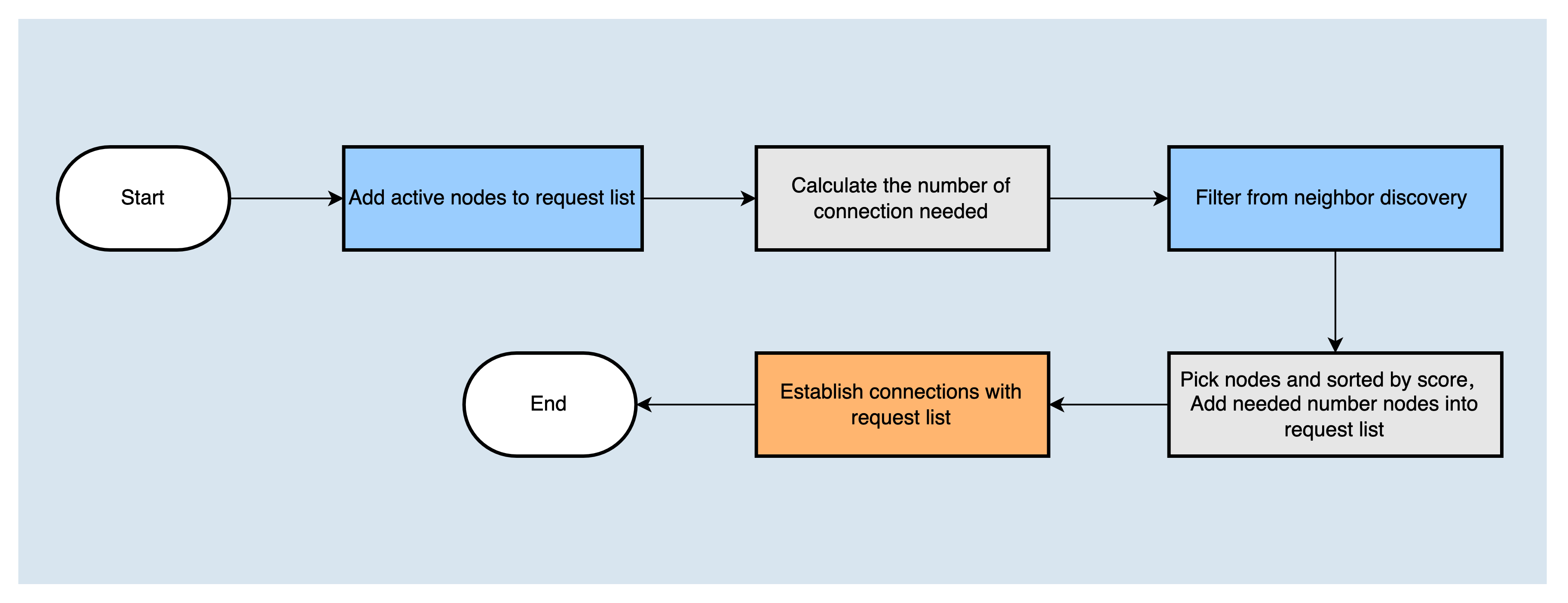
The TCP connection can be mainly divided into two steps: first, determine the node list which the node will establish a connection with. The list needs to contain the active nodes that have not successfully established a connection, and then calculate the number of connections that also need to be established, and filter out the nodes from discovered neighbors according to the node filtering strategy, then score and sort them according to the node scoring strategy, and the corresponding number of nodes with the highest score is added to the request list. Finally, TCP connections are established with the nodes in the request list.
Node Filtering Strategy
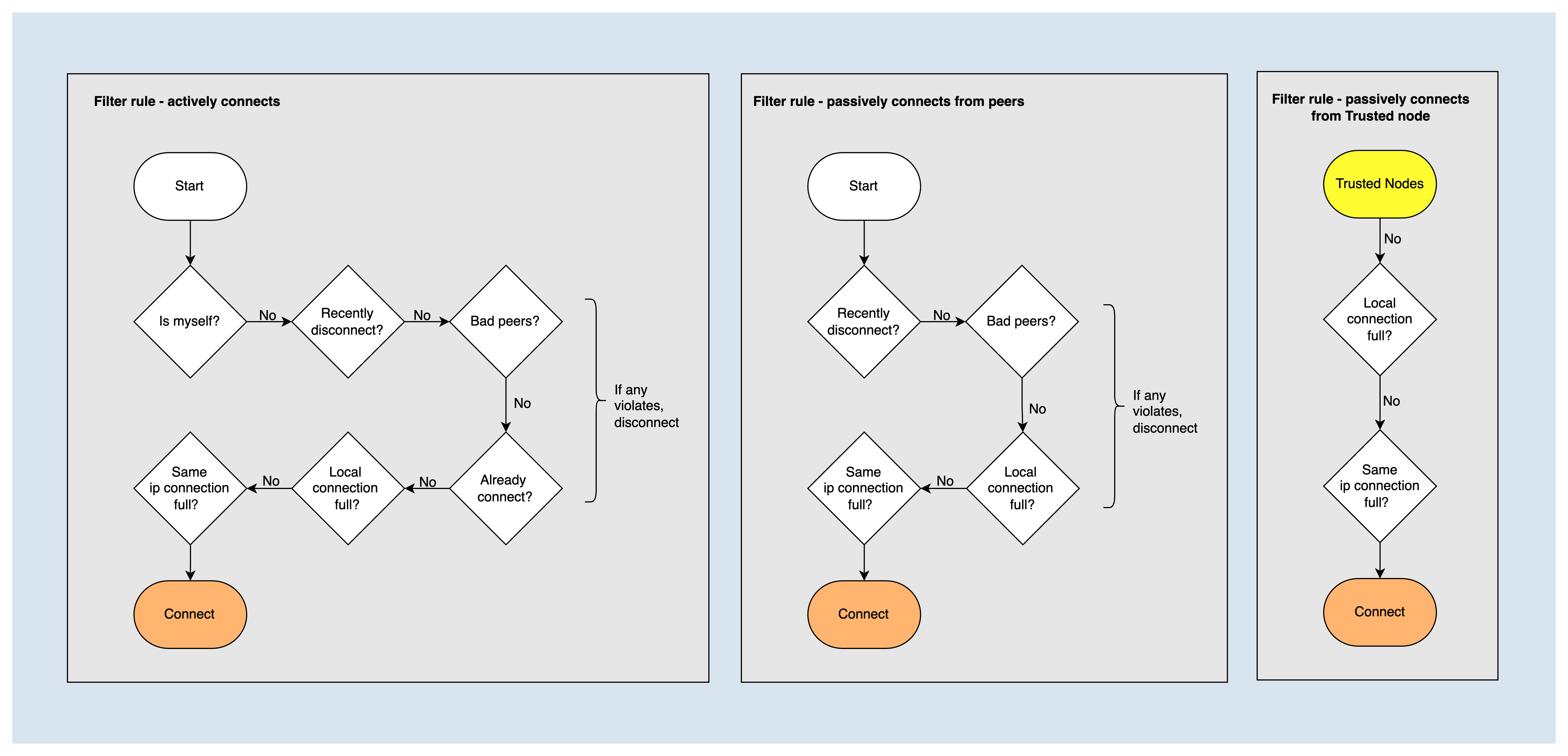
When establishing a node connection, it is necessary to filter out the following types of nodes and determine whether the node's own connection number has reached the maximum value.
- Myself
- Nodes in the recentlyDisconnectedNodes list
- Nodes in badNodes list
- Nodes that have already established a connection
- The number of connections established with the node IP has already reached the upper limit (maxConnectionsWithSameIp)
But for trusted nodes, some filtering policies are ignored and connections are always established.
Node Scoring Strategy
The node score is used to determine the priority of nodes to establish a connection. The higher the score, the higher the priority. Scoring dimensions include:
- Packet loss rate: The lower the packet loss rate, the better the communication quality. The score is inversely proportional to the packet loss rate. The highest score is 100 and the lowest is 0.
- Network delay: The smaller the network delay, the better the network quality. The score is inversely proportional to the average network latency. The highest score is 20 and the lowest is 0.
- TCP traffic: The larger the TCP traffic, the more active the communication. The score is proportional to the TCP traffic, with a maximum score of 20 and a minimum of 0
- Disconnection times: The fewer disconnection times, the more stable the node is. The score is inversely proportional to the number of disconnections. The score is 10 times the number of disconnections.
- Handshake: Nodes that have been handshake successfully before indicate that they have the same blockchain information, so it is preferred to establish a connection with them. When the number of successful Handshakes is greater than 0, the Handshake score is 20, otherwise, the score is 0.
- Penalty state: A node in the Penalty state has a score of 0 and does not participate in scoring in other dimensions. The following situations will be regarded as in the Penalty state:
- Node disconnection time is less than 60s
- The node is in the badNodes list
- Inconsistent blockchain information
When calculating the node score, first determine whether the node is in the Penalty state, if so, the score is counted as 0, otherwise, the node score is the sum of the scores of each dimension.
Handshake
After the TCP connection is successfully established, the node that actively initiates the TCP connection request will send a handshake message P2P_HELLO to the neighbor node, in order to confirm whether the blockchain information between the nodes is consistent and whether it is necessary to initiate the block synchronization process.
When the neighbor node receives P2P_HELLO, it will compare with the local information, such as checking whether the p2p version and the genesis block information are consistent. If all the check conditions are passed, it will reply to the P2P_HELLO message, and then perform the block synchronization or broadcast; otherwise, it will disconnect the connection.
Channel Keep-Alive
Channel keep-alive is accomplished through P2P_PING, P2P_PONG TCP messages. When a node establishes a TCP connection with a neighbor node and handshakes successfully, the node will open a thread pingTask for the connection and periodically send P2P_PING messages to maintain the TCP connection, which is scheduled every 10s. If the P2P_PONG message replied is not received within the timeout period, the connection will be terminated.
Block Synchronization
After completing the handshake with the peer node, if the peer node's blockchain is longer than the local blockchain, the block synchronization process syncService.startSync will be triggered according to the longest chain principle. The message interaction during the synchronization process is as follows:
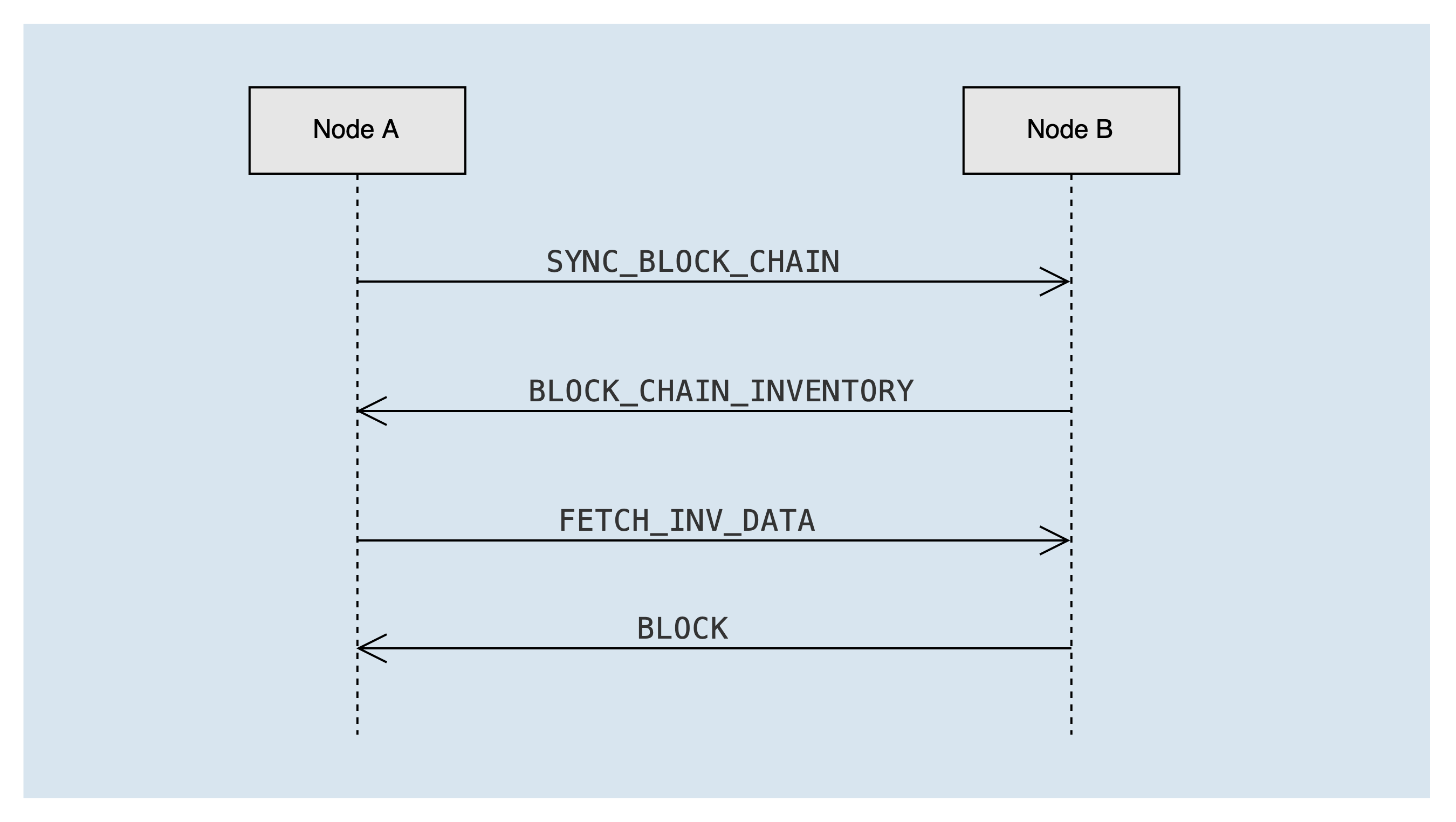
Node A sends an SYNC_BLOCK_CHAIN message to peer node B to announce the blockchain summary information of the local chain. After the peer node B receives it, it calculates the list of missing blocks of node A, and sends the lost block ID list to node A through the BLOCK_CHAIN_INVENTORY message, carrying a maximum of 2000 block ids at a time.
After node A receives the BLOCK_CHAIN_INVENTORY message, it gets the missing block id, and sends a FETCH_INV_DATA message to node B asynchronously to request the missing block, up to 100 blocks at a time. If there are still blocks that need to be synchronized (that is, the remain_num in the BLOCK_CHAIN_INVENTORY message is greater than 0), a new round of block synchronization process will be triggered.
After node B receives the FETCH_INV_DATA message from node A, it sends the block to node A through the BLOCK message. After node A receives the BLOCK message, it asynchronously processes the block.
Blockchain Summary and List of Missing Blocks
Below will take several different block synchronization scenarios as examples to illustrate the generation of the blockchain summary and the lost block ID list.
- Blockchain summary: an ordered list of block IDs, including the highest solidified block, the highest non-solidified block, and the blocks corresponding to the dichotomy.
- List of missing blocks: The neighbor node compares its own chain with the received blockchain summary, determines the missing blocks list of peers, and returns a set of consecutive block IDs and the number of remaining blocks.
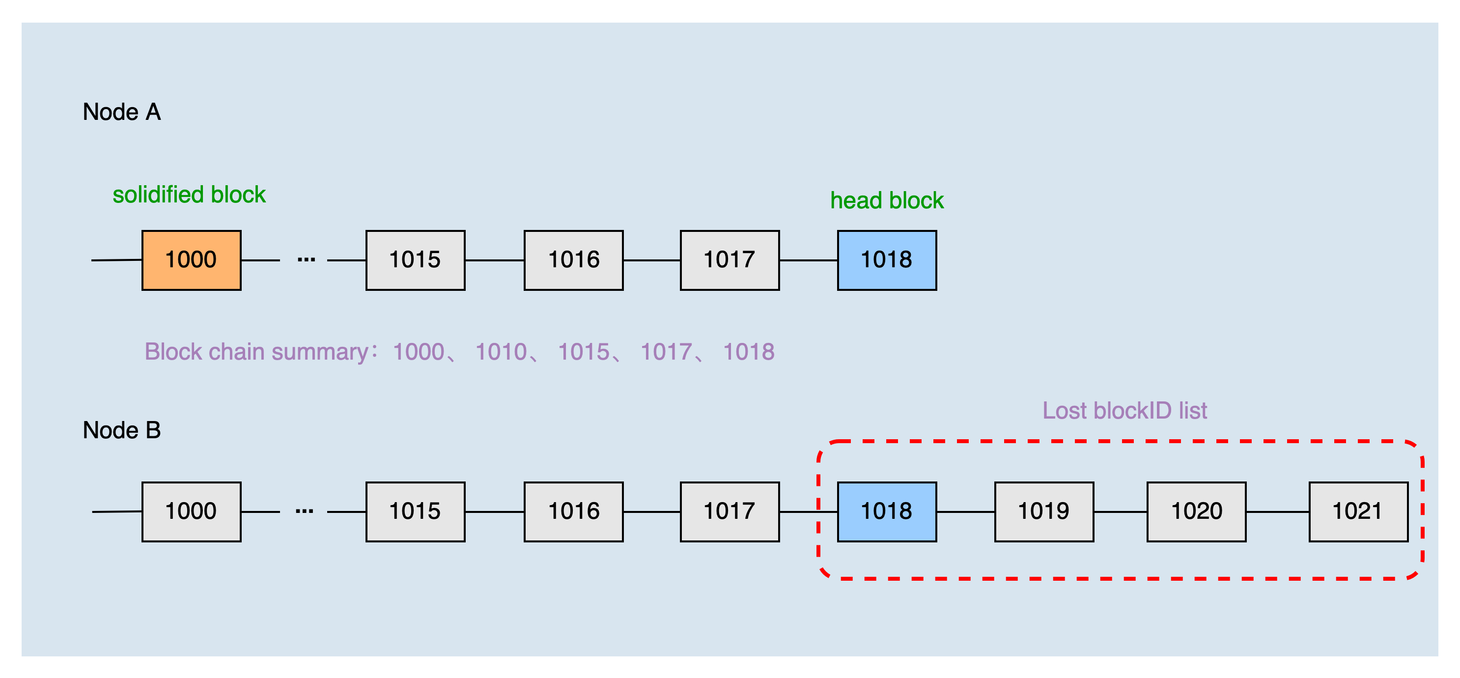
Normal Synchronization Scene
The height of the local header block is 1018, and the height of the solidified block is 1000. The two nodes have just established a connection, so the height of the common block is 0. The local blockchain summary of node A obtained by the dichotomy is 1000, 1010, 1015, 1017, and 1018.
After node B receives the blockchain summary of node A, combined with the local chain, it can produce the list of blocks that node A lacks: 1018, 1019, 1020, and 1021. Then, node A requests to synchronize blocks 1019, 1020, and 1021 according to the list of missing blocks.
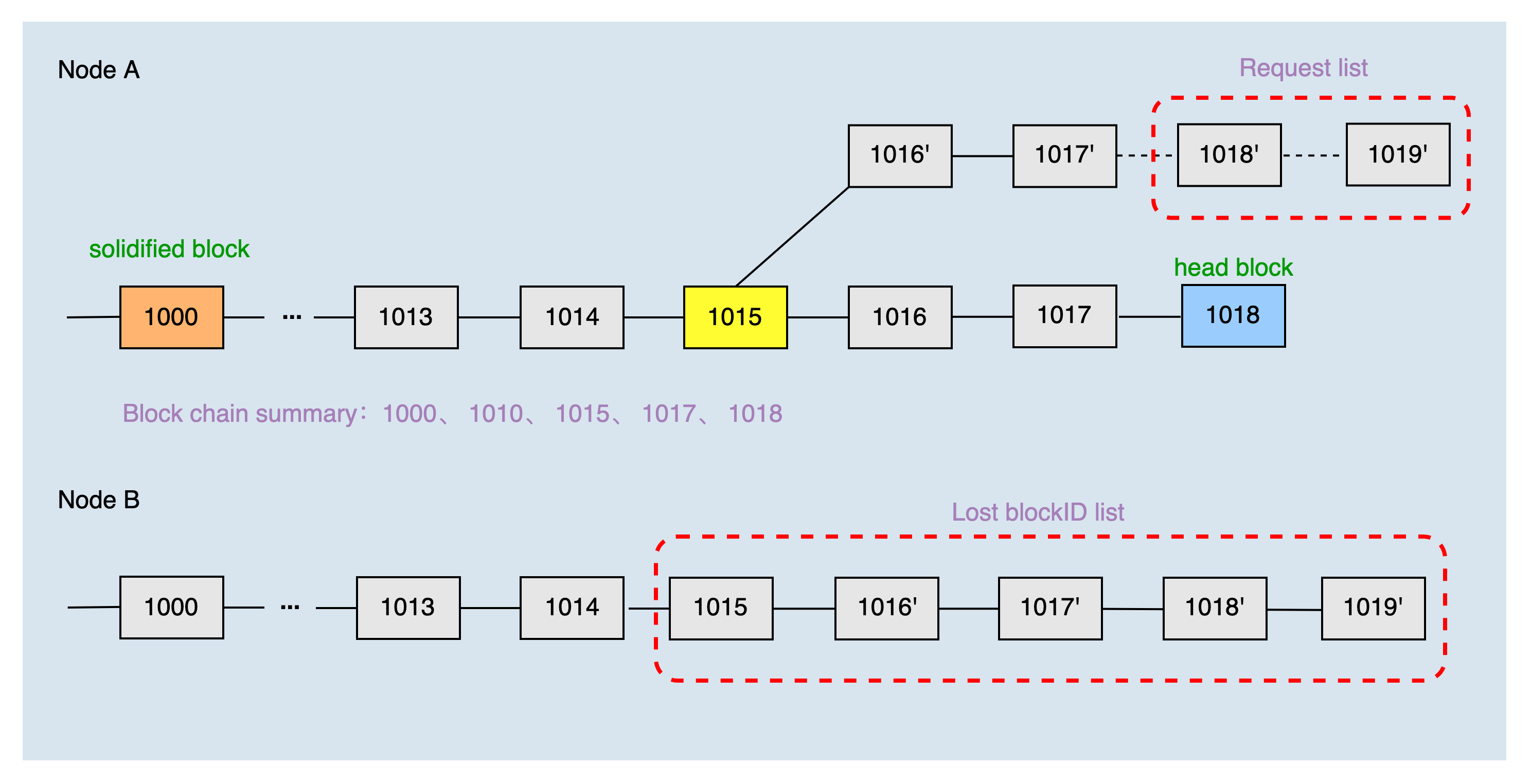
Chain-Switching Scene
The head block height of the local main chain is 1018, and the height of the solidified block is 1000. The two nodes have just established a connection, so the height of the common block is 0. The local blockchain summary of node A obtained by the dichotomy is 1000, 1010, 1015, 1017, and 1018.
After node B receives the chain summary of node A, it finds that the local main chain is not the same as the main chain of node A, compares the chain summary of node A and finds that the common block height is 1015, then it computes the list of blocks that node A lacks are 1015, 1016', 1017', 1018', and 1019'. Then, node A requests to synchronize blocks 1018' and 1019' according to the list of missing blocks.
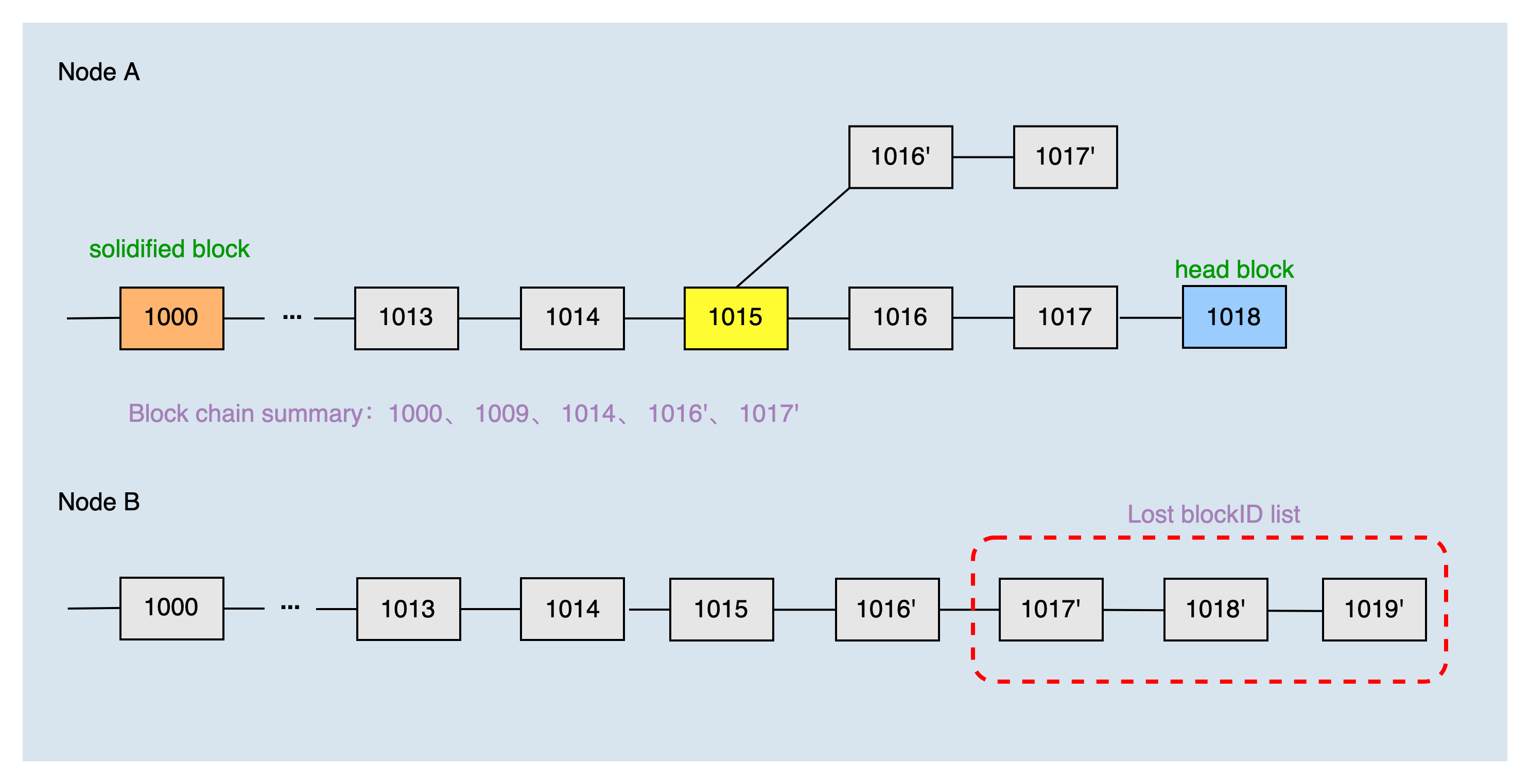
In another switching chain scenario, the height of the local main chain header block is 1018, the height of the solidified block is 1000, and the common block is 1017', which is located on the fork chain. The local blockchain summary of node A obtained by the dichotomy is 1000, 1009, 1014, 1016', and 1017'.
After node B receives the chain summary of node A, combined with the local chain, it can produce the list of blocks that node A lacks 1017', 1018', and 1019'. Then, node A requests to synchronize blocks 1018', and 1019' according to the list of missing blocks.
Block and Transaction Broadcast
When the super representative node produces a new block, or the fullnode receives a new transaction initiated by the user, the transaction & block broadcasting process will be initiated. When a node receives a new block or new transaction, it will forward the corresponding block or transaction, and the forwarding process is the same as that of broadcasting. The message interaction is shown in the following figure:
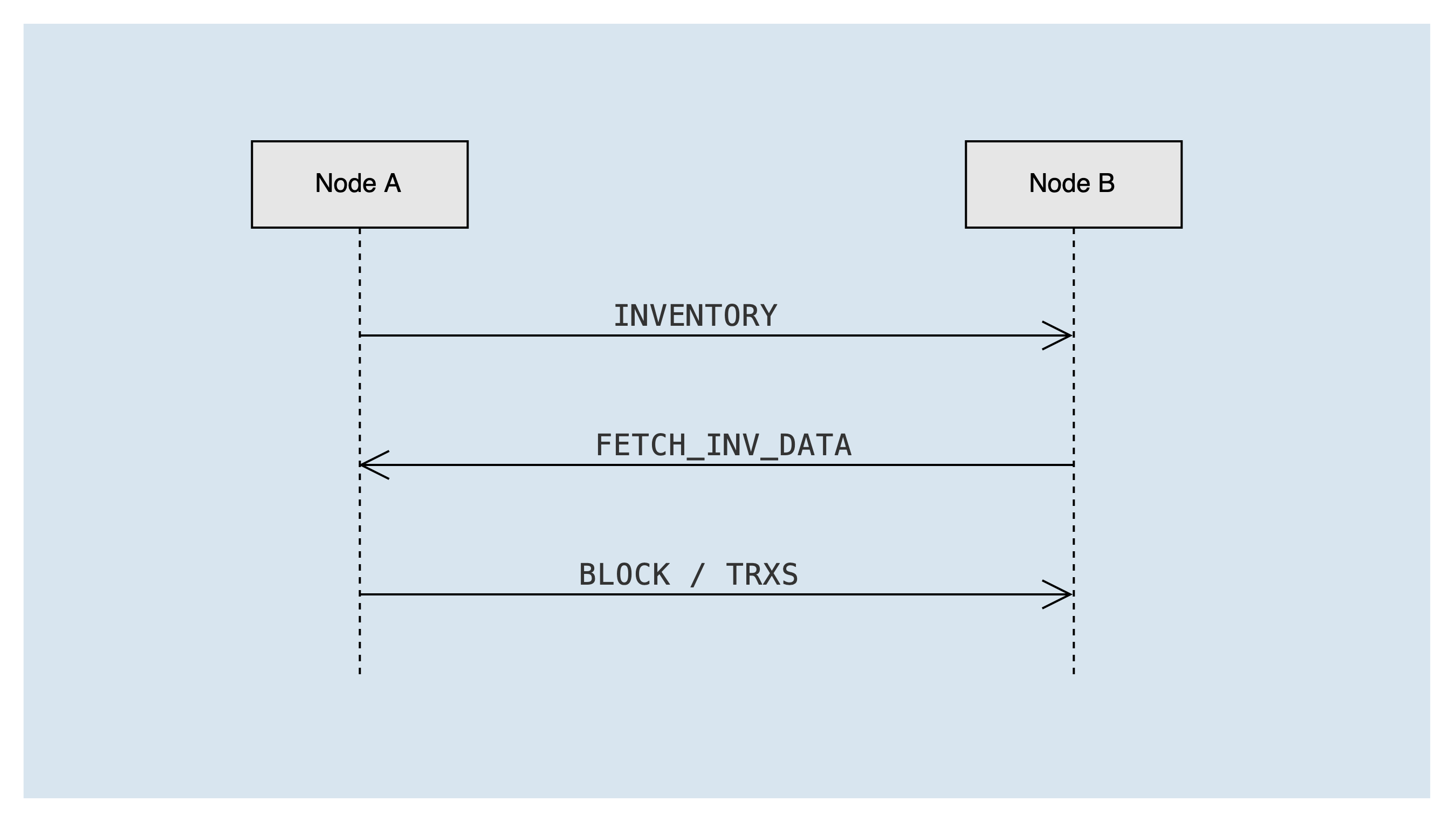
The types of messages involved include:
INVENTORY- broadcast list: list of block or transaction idsFETCH_INV_DATA- the list data that the node needs to get: block or transaction id listBLOCK- block dataTRXS- transaction data
Node A sends the transaction or block to be broadcast to Node B via the INVENTORY list message. After node B receives the INVENTORY list message, it needs to check the status of the peer node, and if it can receive the message, it puts the blocks/transactions in the list into the "to be fetched queue" invToFetch. If it is a block list, it will also trigger the "get block & transaction task" immediately to send a FETCH_INV_DATA message to node A to get the block & transaction.
After node A receives the FETCH_INV_DATA message, it will check whether an "INVENTORY" message has been sent to the peer. If it has been sent, it will send a transaction or block message to node B according to the list data. After node B receives the transaction or block message, it processes the message and triggers the forwarding process.
Summary
This article introduces the implementation details related to the P2P network, the lowest level module of TRON, including node discovery, node connection, block synchronization, and the process of block and transaction broadcasting. I hope that reading this article can help developers to further understand and develop java-tron network-related modules.